based wireless digital stethoscope Circuit Diagram So without further ado let's get started. How Does Wireless Digital Stethoscope Work? Before we go any further in the article, let's discuss how this circuit works. In order to get the heartbeat data, we will first get a stethoscope and cut it in half to fit a condenser microphone, so that we could get the heartbeat sound from the stethoscope. The DIY Wireless Digital Stethoscope project aims to create a modern stethoscope using wireless communication and digital signal processing. This project allows for remote monitoring of heart and lung sounds, offering medical professionals an enhanced tool for diagnosis and patient care. In this video you have seen about the digital stethoscope and how to build your own digital stethoscope.And I also explained what are the components required

Hello, i am making an electronic stethoscope. But iam facing several problems in it. I am using CM-01B Piezoelectric sensor . Here are the components of my circuit below. My circuit: 1) Charge amplifier using INA128P 2) Voltage amplifier using A620AN 3) BANDPASS Filter using TLC2272CP 4) LM386

Build Your Own Digital Stethoscope Circuit Diagram
A medical device called a stethoscope is used to hear sounds made by the body, primarily by the heart or lungs. One of the crucial medical tools that influence remote or self-diagnosis in the medical field is the electronic stethoscope. This is Electronic Stethoscope circuits.Usually the stethoscope is a medical device that listens to the heartbeat.We can make it with least amount of parts.

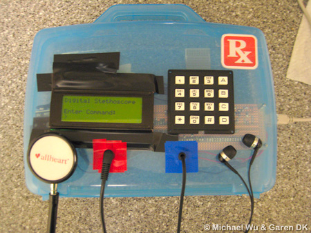
The purpose of this project was to design and implement a digital stethoscope to serve as a platform for potential computer aided diagnosis (CAD) applications for the detection of cardiac murmurs. The system uses a custom-built sensor to capture heart sounds at 8 kHz and converts them to electrical signals to be processed by an ATmega644 microcontroller. The captured signals are outputted via

electronic stethoscope Circuit Diagram
The circuit diagram of the proposed electronic stethoscope amplifier is designed using two stages, one consisting of the opamp based tone control circuit, and the integrated proper amplifier stage.